Sample transfer
Basics of sample holder
(adapted from text by YN)
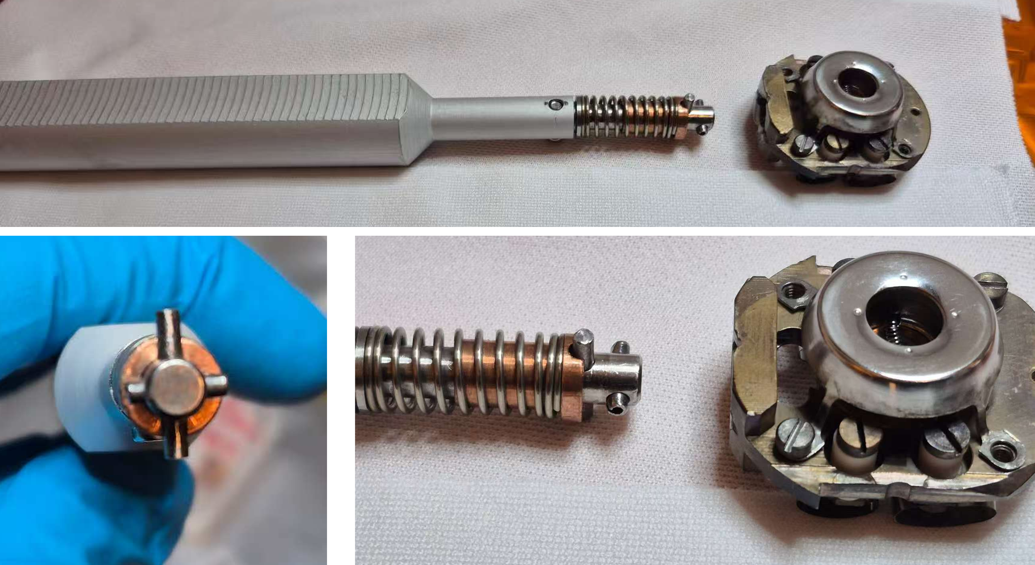
The transfer tip is designed as a cross formed by two perpendicular pins.
Short pins are in front and fixed in position.
Long pins in the back are attached to a spring, which can be further pressed backwards.
The backside of the sample holder can be locked by these pins.
A demonstration of the locking mechanism can be found in this video.
The mounting tip shown there has the same geometry as the transfer arm tip inside the endstation. The main difference is the spring stiffness - the transfer arm tip is less stiff, requiring extra care during locking and unlocking. Another complication regarding transfer arm tip is that it is not perfectly concentric, meaning a 180° rotation may slightly shift the tip. This can make insertion of removal of tip from the sample holder slightly more difficult and risky.
Below, the critical points for using the loadlock, preparation and main chamber will be explained. Use mirror (and future cameras) to help guide the transfers.
Locking procedure of sample holder
To lock the sample holder: (included in video)
Insert the short pins into the slightly elongated hole on the backside of the sample holder
Push the tip gently so that the short pins move into the hollow space inside the holder.
Rotate the tip for 90°.
Ensure the long pins align with the groove on the backside of the hole. The spring will then automatically press the long pins into the groove.
Release the push. The two crossed pins now lock the sample holder firmly to the tip.
You may now safely remove the sample holder from any sample stage (loadlock, prep and main chamber)
Unlocking procedure of sample holder
To unlock and realise the tip: (included in video)
Push the tip gently so the short pins enter the hollow space again.
While keeping light pressure, rotate the tip for 90°. This moves the long pins moves of the groove and short pins being aligned with the orientation of the elongated hole.
The spring’s retraction will provide feedback, indicating the tip is free. Gently pull the short pins out of the hole.
Caution
Ensure the short pins are truly free of friction before pulling it out.
If it catches the edge of the hole, the sample holder may lift out of the stage.
Always keep your eyes on the sample holder and the pins during locking or unlocking.
Changing sample in Loadlock
Caution
Frequently check the pressure of chambers. After insertion, remember to check the pressure of prep chamber in case of leakage.
Venting
A demonstration of venting load lock can be found in this video.
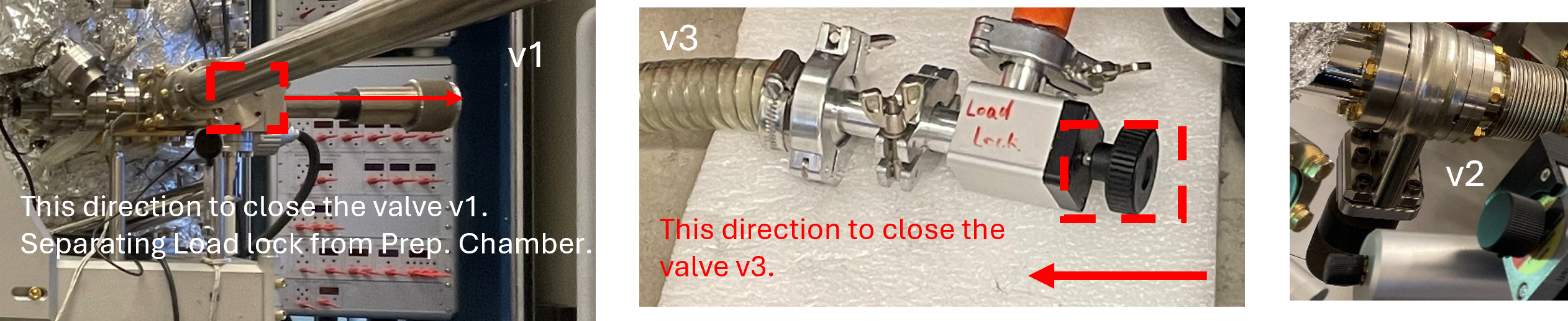
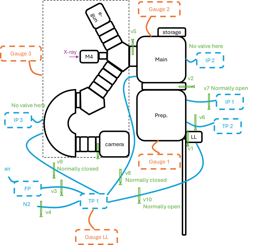
Check that the valve from load lock to prep chamber (v1), and valve from prep chamber to main chamber (v2), and valve to forepump (v3) are closed.
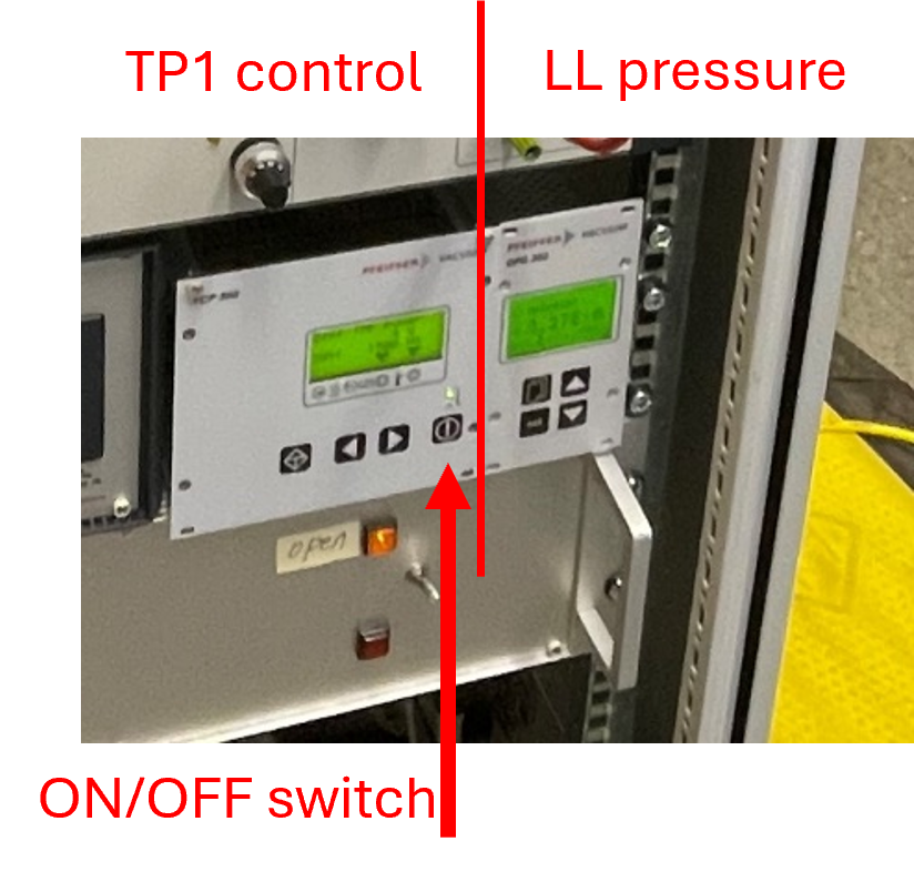
Turn off the small turbo pump (TP1): The green light above the switch will start blinking and speed will decrease from 1500 Hz. Can hear the sound of deaccleration of TP1.
Loose the bolts of load lock but keep them in the holes.
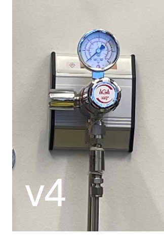
Set the nitrogen gas regulator (v4) around 0.4-0.6 on the low-pressure side (clockwise to open). You will hear the nitrogen flowing through the load lock.
Fully remove the load lock bolts and flange when LL pressure reads 1000 mbar – insert sample (gloves must on) – stop the nitrogen flow via v4 – close the load lock bolts (one up right, one down left) and flange. Hand tighten the two bolts instead of using a wrench, to avoid over-tightening.
Pumping down after sample insertion
A demonstration of pumping load lock can be found in this video.
Slowly open valve to forepump (v3) and switch on small turbo pump TP1. Hear the noise from forepump pumping.
As the pressure decreases, hand-tightening the load lock bolts again (without wrench) may be necessary.
Wait until the load lock pressure reads at least 3x10^-6 mbar to transfer the sample into prep chamber. This might take 15-30 minutes.
Leave sample in prep chamber to degas. Remember to close v1 to separate load lock and prep chamber after the sample transfer.
Pratical tips about changing sample in Loadlock
If the loadlock is tighten too much, the sample stage can tilt, making it difficult to insert the sample into the slots or insert the short pins into the elongated hole of the sample holder.
Solutions:
Flip either the sample holder or the tip 180°.
Slightly loosen the loadlock manipulator. Be cautious if the loadlock was vented and always remember to monitor the prep chamber pressure for leaks.
Sometimes the sample holder follows the tip when you try to remove the tip after insertion.
Solutions:
Retract the loadlock manipulator slightly and try again.
Gently wobble/shake the tip in a small amplitude while pulling it out.
Always ensure the sample holder remains correctly seated in its slots and does not drop.
Changing sample in prep chamber
Demonstration video can be found here.
Carefully observe the position of the holder in the prep chamber, as the motor does not have an auto-step function. The scale should reach 286 to accommodate the sample.
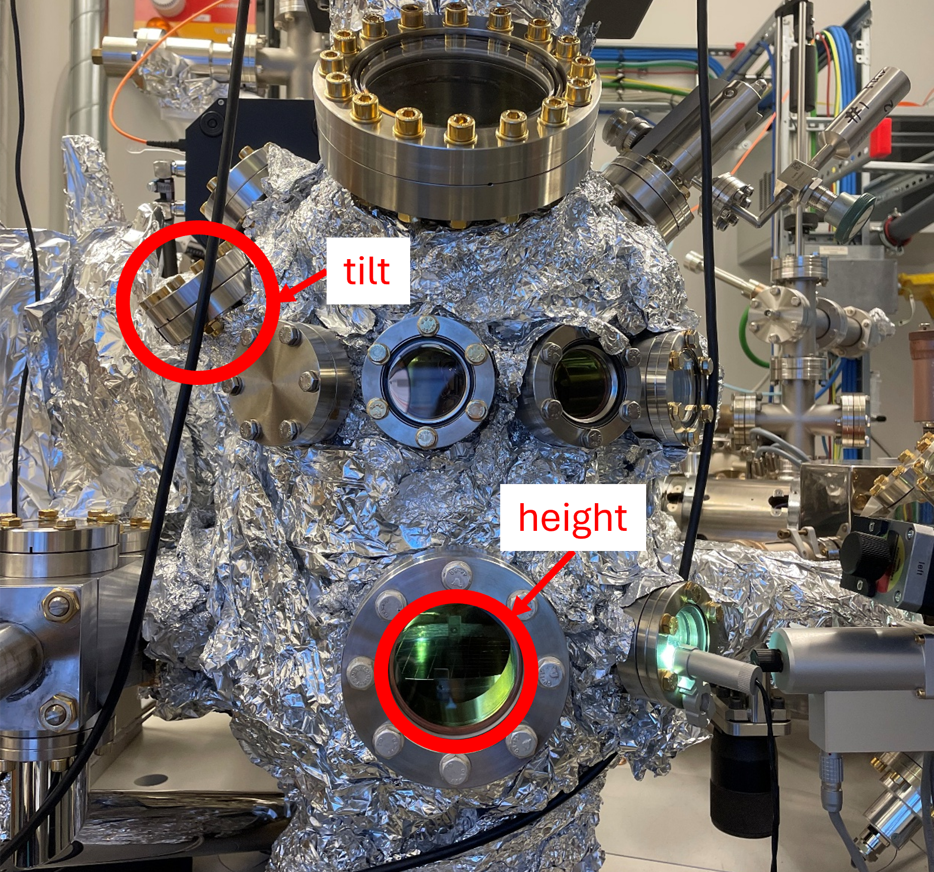
Check the height and tilt of the sample through the two marked windows before insertion.
The transfer must be smooth. If any resistance is felt, stop immediately, as this indicates a misalignment. Do not apply force greater than finger force.
Pratical tips about changing sample in Prep chamber
Similar issues may arise here. Since the preparation-stage position can be freely adjusted (x–y–z), optimizing the stage position is key for the whole process.
Guidelines:
View tip location with respect to the sample stage from two viewports: the front cf63 and the tilted upper cf40 to make sure they fit each other.
After inserting the sample holder, and before unlocking the tip: ensure the sample holder is properly seated in both upper and lower slots of the sample stage. Sometimes it enters only the lower slot and becomes tilted - never unlock the tip in this situation, or the sample holder may fall.
Before removing the sample holder out of the sample stage, confirm via the front cf63 window that the tip is locked.
Transfers should be extremely smooth, either insertion or removal from the sample stage.
If you feel friction, adjust the stage rather than applying force.
Excessive force can damage electrical contacts on the holder or stage.
Changing sample in main chamber
Danger
Turn off the high voltage rack before changing sample!
Caution
Ensure that the tilt is properly initialized by physically verifying it before adjusting the manipulator head, especially if you plan to insert the sample into storage!
Demonstration video can be found here.
Before transferring:
Close the valve to the X-ray beam, turn off the electron gun (-360 V), and either turn off the UV lamp or close its iris entirely, as appropriate.
Initialize the manipulator’s position (X, Y) and tilt to 0 (X, Y, tilt = 0). Double-check the values in both the software and the manipulator head physically. Ensure that the holes are fully exposed and not partially obstructed.
Remove slit and apertures, and double check that the high voltage rack is off!
Please use the red manipulator spacer after retracting the sample to the transfer position. The correct Z position is approximately 0.5 mm (half turn) back from the spacer width.
Before operating the transfer arm, verify the holder’s location in the prep chamber to avoid collisions. Open the valve between the prep chamber and the main chamber, and remember to close it once finished. Always be aware of the transfer arm’s position and any objects in its path, adjusting its orientation as needed.
Pratical tips about changing sample in Main chamber
During insertion/removal:
Monitor via multiple windows during operation, especially top cf63 viewpoints. Before unlocking, ensure the sample holder is fully seated in both the upper and lower slots of the sample stage, and not tilted at an angle.
Notes:
If the microscope has been aligned, most likely the alignment is good enough for measurements after correcting the sample tilt.
The standby mode generally is FOV = 10 µm and STV = 0V.
Schematic Layout of the UHV System
Vacuum suitcase connected to the load-lock
For air-sensitive samples, MAXPEEM offers the option of transferring the sample in argon. One needs to book a chemistry lab with a glovebox (e.g. D3) https://lab-booking.maxiv.lu.se/
Transfer the suitcase, sample cartridge, sample(s), etc. into the glovebox, using the large antechamber
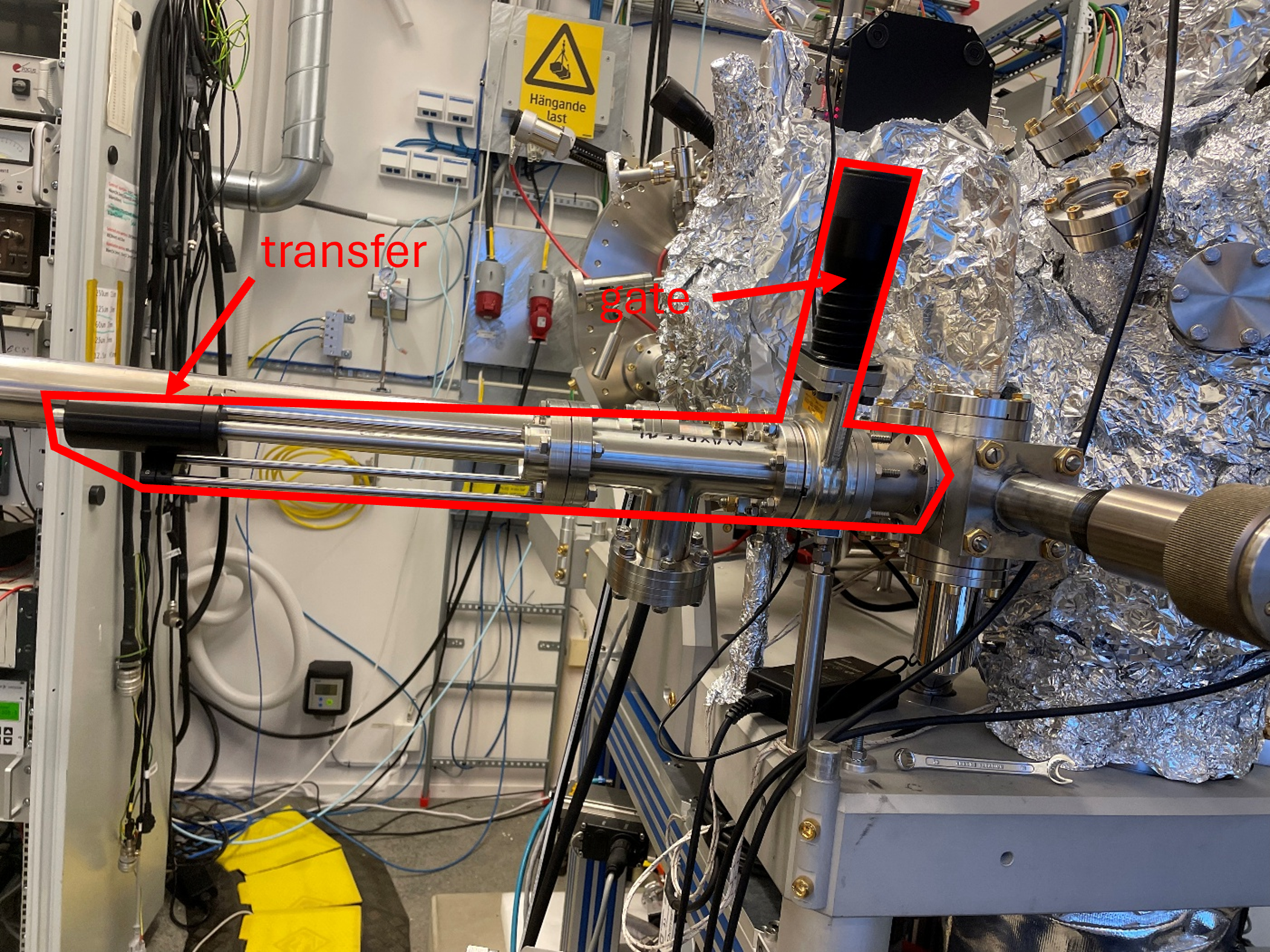
Figure 1. Photo of the suitcase connected to the load lock.
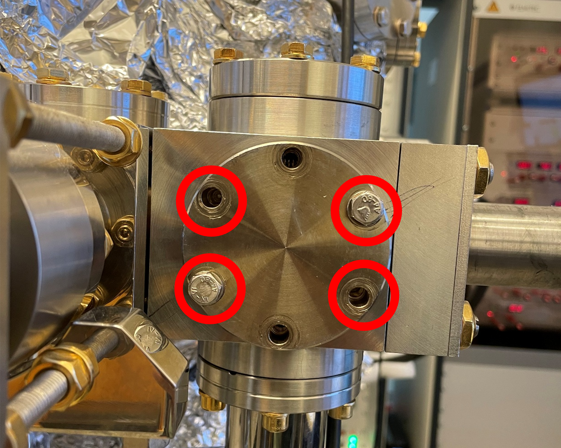
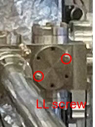
Figure 2. Four screws are needed to fix the suitcase to the load lock.
Vent the load lock, remove the flange and keep the o-ring in. Handle with gloves at all times.
Stop the nitrogen flow.
(two-person operation) Hold the suitcase and align it to load lock. Secure it with four screws. Tighten the screws using a wrench with finger force only (do not overtighten).
Pump down the load lock normally and slowly open the gate of suitcase when the pressure reach 10^-2 level. Transfer the sample into load locak and close the gate.
Transfer the sample into prep chamber when the pressure reads 3x10^-6 mbar.
Vacuum suitcase connected to the prep chamber
This part has not been updated.
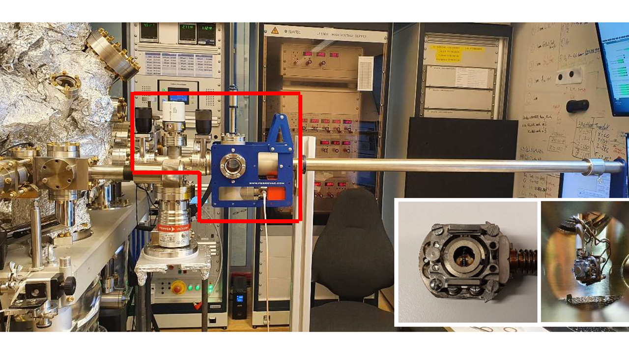
Figure 1. Photo of the Ferrovac UHV suitcase connected to the prep chamber. The inset shows the Elmitec-Omicron adaptor.
In the prep chamber, an Omicron flag-type sample plate can be transferred using an Omicron-Elmitec adaptor via a Ferrovac UHV suitcase.
Mount the sample on sample holder
Install the cartridge in the aluminum holder.
Loosen the four M2 screws holding the sample down.
Remove the sample cover
Remove the sample
Install the new sample
Install the sample cover
Fix the cover with the four screws (suggestion: tighten the screws in an X pattern)
Caution
The tilt on the manipulator can only be adjusted up to +/- 2 degrees. Mount the sample onto the cartridge as flat as possible.