Operating the prep chamber
Sputtering with argon
Caution
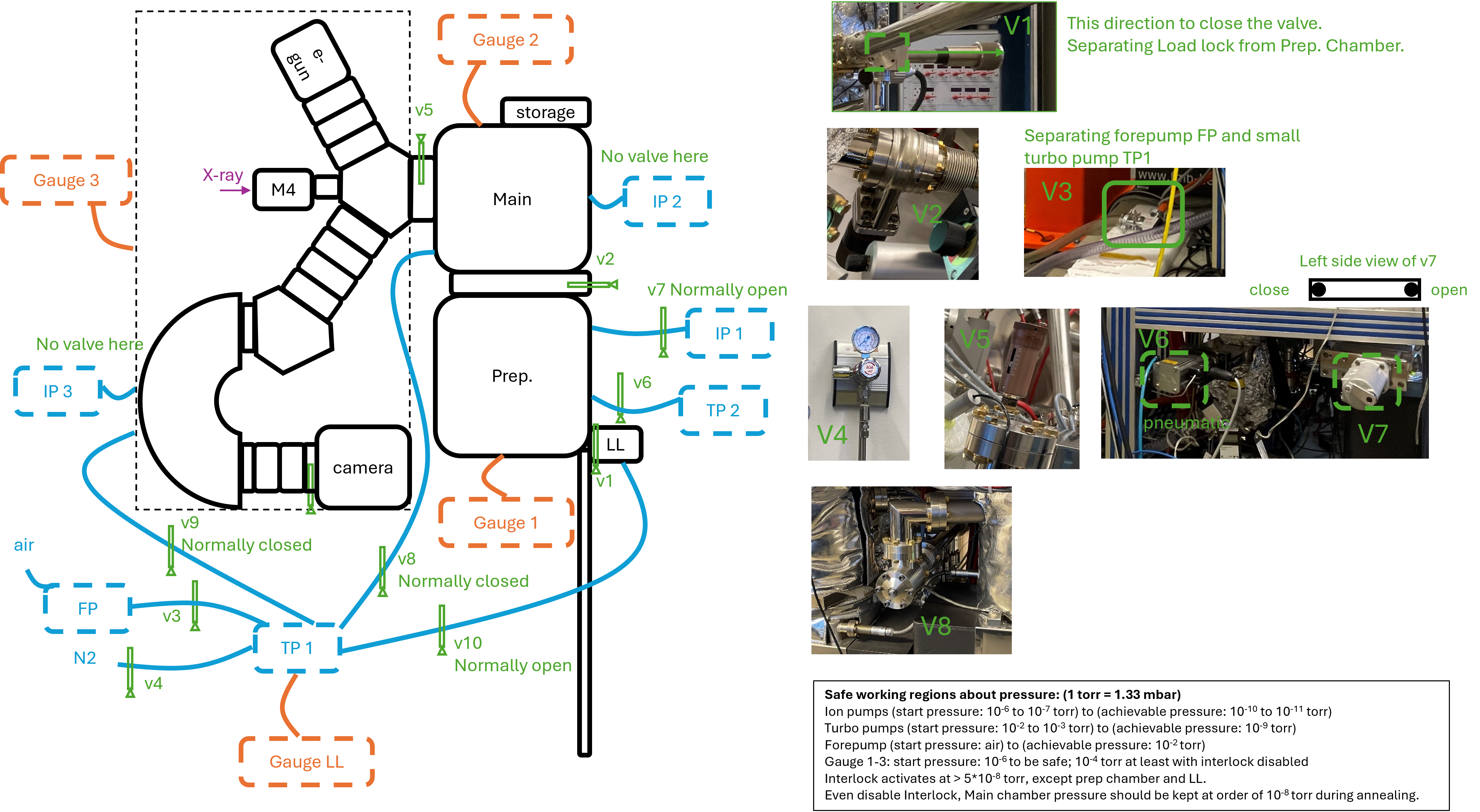
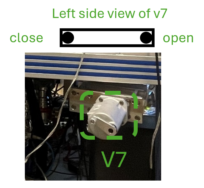
Make sure the v7 is closed so that IP1 will not be affected by gas insertion.
Ensure the mini-cylinder connected to the ion source is labeled with argon. Check if argon is clean with Mass spectrometry (spectrum with argon – spectrum without argon).
Rotate the sample 90° to face right side, so that the sputter will happen at 45° incident; remember the direct to rotate the manipulator so that later it will be rotate back instead of going through a circle rotation; when changing the height of manipulator always make sure it is clear to move, so that nothing will be bent; the motor of manipulator will not automatically stop, so always be careful and aware of the manipulator location.
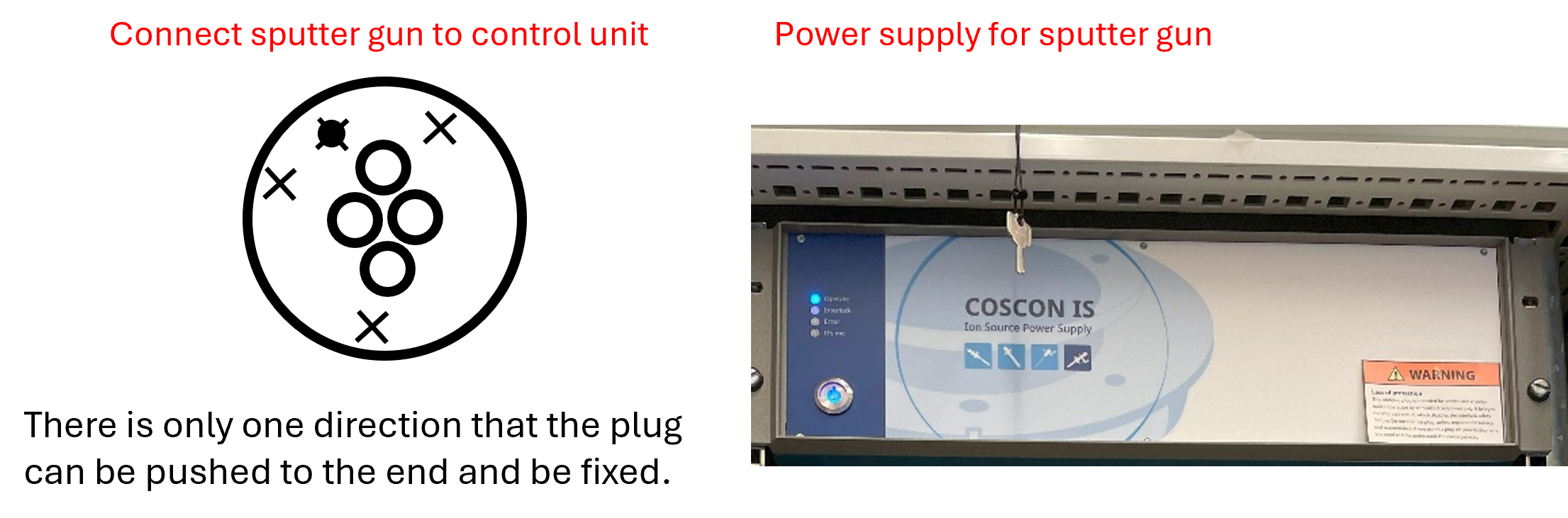
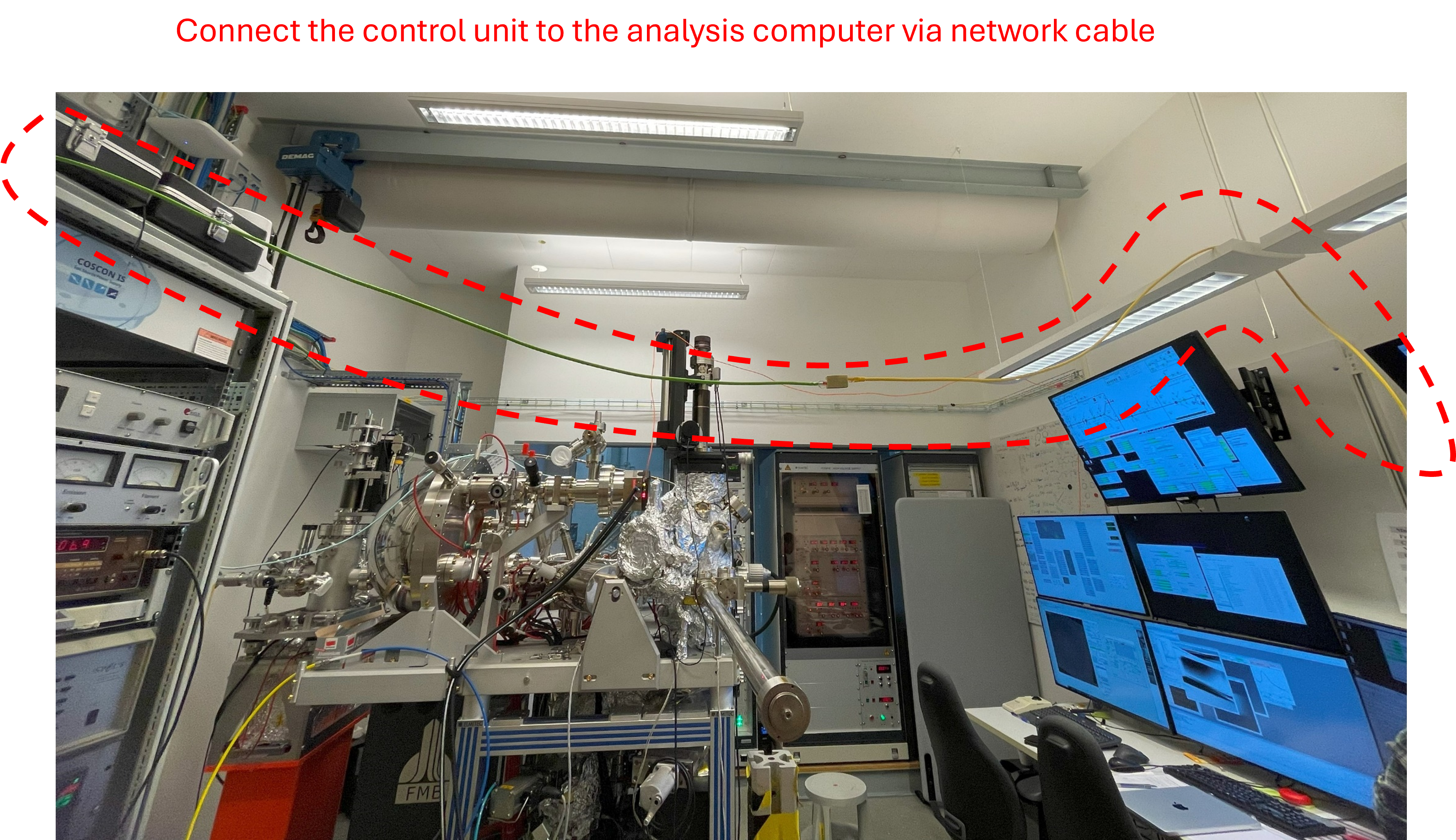
Link the sputter gun with control unit. Connect to the power supply and turn on the power supply (top shelf), and the four lights will be blinking on and off.
Ensure the Ethernet cable from the Specs supply is connected to a cross-over Ethernet cable that’s plugged into the User Data Analysis workstation.
Start the Specs Prodigy software on the workstation and connect the sputter gun by clicking on the box.
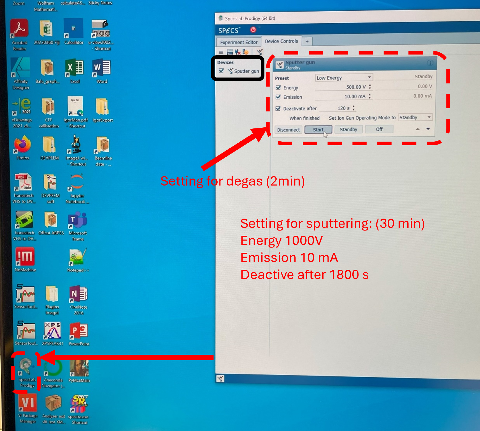
Degas for 2 min while watching the pressure, which might reach 10^-9 torr.
Start argon flow while watching the pressure: slowly open the gaskets for argon, and stop opening it while reach 10^-8 torr and let it slowly reach 10^-7 torr.
Change the setting for sputtering operation and there should be some emission current. Maximize the emission current to ~ 5.0 mA by adjusting the X and Y of manipulator in prep. chamber, instead of rotation. Argon flow can be adjusted a bit if needed.

The pressure increases to 2x 10^-6 torr and emission current to ~ 6.6 mA are also fine.
Check the connection of wires on the backside of shelf if there is no emission current.
Annealing/Degassing the sample in the prep chamber
Remember to close argon flow before annealing. Default parameters: Filament current = 2.65 A and voltage = 50 V for annealing for ~ 30 min. Remember to set timer for this.
Information about details refers to this page.
In-glovebox crystal cleaving, and air-free transfer to the microscope
The general idea is to:
Bring the sample, vacuum suitcase, a sample cartridge, and the necessary hand tools into a glovebox (for example, the argon glovebox in the D3 lab)
Cleave the crystal with a scalpel blade.
Mount the freshly cleaved crystal into the sample cartridge
Load the sample cartridge into the vacuum suitcase, close the gate valve in argon.
Bring the suitcase out of the glovebox, connect to the load lock, and pump down.
In-vacuum post-cleaving of the crystal
This method is still under development. Talk to the beamline staff about it. Ensure the crystal sample will not outgas substantially in vacuum. If the sample needs to be degassed first (due to, for example, trapped water in the crystal since the crystal was grown in air), one can use the vacuum oven at DanMAX sample environments and equipment.
The general idea is to:
Glue the crystal sample to a rigid, electrically conductive plate with EPO-TEK H20E vacuum-compatible silver epoxy. The conductive plate could be made out of copper, and should be sized appropriately (14 mm diameter max. for a disc, 2.5 mm max. thickness). The standard epoxy recipe involves mixing parts A and B in a 1:1 ratio and curing the epoxy at 100C, for 1 hour, on a hotplate in air.
Glue a cylindrical post to the vacuum-facing side of the crystal, using EPO-TEK H21D epoxy with parts A and B mixed in a 10:1 ratio. Cure the epoxy at 100C on the hotplate for 1 hour. Ensure the length of the post will not collide with the load-lock cartridge holder, once the sample is assembled into the sample cartridge.
Cleave the crystal in-vacuum by carefully extending a wobble stick into the path of the transfer rod, and hitting (just) the post with the edge of the wobble stick.
Talk to the beamline staff about making the posts from 316 stainless steel.
Note
The diameter of the post, diameter of the opening in the cap, epoxy curing time, etc. are all parameters that need to be optimized for each sample
Vent and Bake preparation chamber
If any part of this procedure is unclear, consult a beamline scientist for guidance.
1. Prepare the Manipulator and Valves
Move the manipulator to a higher position using the motor.
The bellow should be long and not compressed.
Close the valve between the main chamber and the preparation chamber (V2).
Close both valves from the small turbo pump (TP1) to:
the main chamber (V8, normally closed) and
the column (V9, normally closed).
Close the big gate valve (V6) between the preparation chamber and the big turbo pump (TP2).
Close the big gate valve (V7) between the preparation chamber and the big ion pump (IP1).
Switch off the ion gauge of the preparation chamber: press “channel” and then press “left arrow”
2. Venting the Loadlock and Preparation Chambers
The images for steps can be found in the venting loadlock.
Open the valve (V1) between the loadlock and preparation chambers halfway.
Vent the loadlock and preparation chambers as follows:
Close the valve (V3) to the forepump.
Switch off the turbo pump.
Open the N₂ line to 0.4–0.6 bar.
Loosen the two bolts on the loadlock flange halfway.
Wait until the turbo pump controller vents the chamber slowly.
The flange will lift automatically once the pressure exceeds 1 bar.
3. Perform the Work
Carry out necessary installation or repair work inside the preparation chamber.
4. Pump Down Procedure
After the work is done, pump down the chamber following the normal loadlock procedure:
Switch off the N₂ supply.
Close the CF40 flange using two bolts tightened by fingers.
Open the valve to the forepump.
Switch on the turbo pump once the pressure drops below 40 mbar.
Wait for ~30 minutes.
When the turbo pressure is better than 1×10⁻⁵ mbar,
Switch on the ion gauge (press the “channel” button, then the right arrow).
Open the big gate valve (V6) between the big turbo pump and preparation chamber.
The pressure should drop immediately.
You can then close the loadlock valve (V1) and continue pumping only the preparation chamber with the big turbo.
5. Bakeout Preparation
Wrap the manipulator with approximately 2 m of heating tape.
First wrap the bellow with a layer of Aluminium foil, then apply the heating tape.
If any equipment (e.g., evaporator) is installed, wrap it with a separate heating tape.
Cover all glass viewports/windows with Aluminium foil.
Remove all unbakeable cables and devices, such as the manipulator motor.
Cover all heating tapes and exposed chamber areas with Aluminium foil.
6. Electrical Setup
Connect the movable bakeout power supply to the 3-phase wall socket.
Plug in all heaters, including:
Heating tapes
Long transfer arm heater
7. Final Pumping and Bakeout
When the pressure reaches the low 10⁻⁷ mbar range,
Open the gate valve (V7) between the preparation chamber and the ion pump (IP1).
Start the bakeout sequence:
Switch on the movable power supply.
Start the 12-hour timer.
Switch on all individual power supplies for the heaters.
Monitor temperature and pressure closely during the first 2 hours and adjust power if needed.