Operating the microscope
Danger
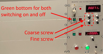
The microscope utilizes high voltages (~ 20 kV). Under normal operating conditions, users do not need to worry about electrical shock. If you experience an electrical shock, immediately switch off the high voltage (green button) and report the incident to your local contact.
For detailed alignment, one can start with UV-PEEM for aligning intermediate column and image column with field of view typically > 50 µm, without influence from illumination column.
For simple alignment, one can directly start with LEEM or XPEEM with a smaller field of view and do steps 16, 1→15. Repeat steps (16, 1, 2) as needed during the initial process.
The setup inherited from the previous week is normally well-aligned, allowing for a simple alignment check first. During alignment, one can always use ‘undo’ to return to previous setting of lens, but not manipulator motors.
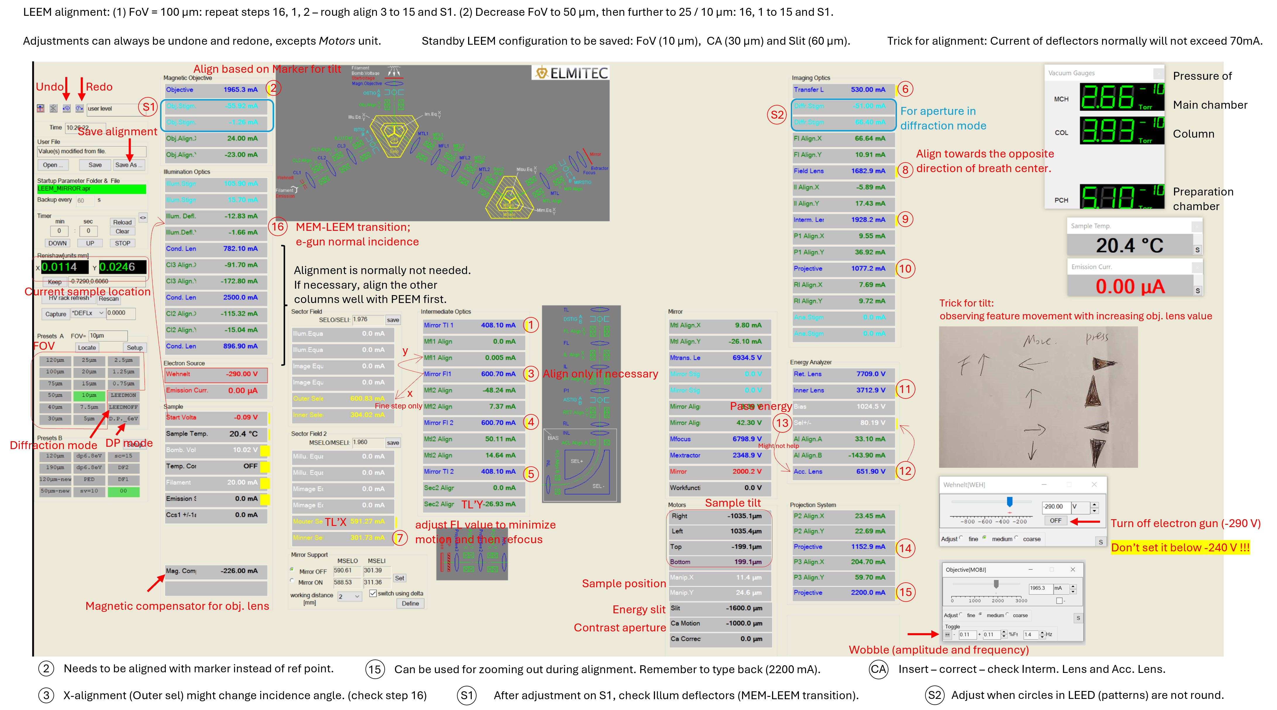
The descriptions of these steps are explained in detail at the end of this page, as well as about slit and aperture insertion. The screenshot of LEEM2000 and the file detailing the alignment steps are available for download on the manual page.
Modes
Modes |
ILA |
SAA |
CA |
ES |
Comment |
|---|---|---|---|---|---|
Imaging mode (LEEM, PEEM) |
x |
x |
ES must be inserted in LEEM mode |
||
Dispersive plane mode (XPS) |
x |
x |
ES must be removed to start acquisition |
||
µ-ARPES (PED) |
x |
x |
No CA is needed, ES 25 µm or smaller |
||
LEED |
x |
(x) |
IA is preferred over SAA, ES is optional |
ILA : Illumination Aperture
SAA : Selection Area Aperture
CA : Contrast Aperture
ES : Energy Slit
Frequently used parameters: Select area aperture = 100 / 50 µm (real image size = SAA/20), Contrast aperture = 30 µm, Energy slit = 60 µm, Illumination aperture = 30 µm.
For detailed info about slit and aperture insertion, refer to the section below with the same name.
Change setup from LEEM to another mode
XPEEM
From LEEM alignment to XPEEM measurement
Close electron gun by set Wehnelt voltage to OFF value (-360 V).
Set start voltage to a value like 1.5 V instead of 0.
Open x-ray valve and align beam with observing image. Refocus with objective lens and adjust Obj. Stigmator. Maximize signals with adjusting start voltage.
If feature has shadow, it means Field Lens X, Y needs adjustment. And likely signal will become stronger if aligned well.
Sometimes checking value of Acc. Lens is needed, but normally not.
Micro-XPS (Dispersive mode) measurement
Save the LEEM setting in case of changing back to imaging mode later, normally with FOV ~ 10 µm.
Insert SAA (e.g., 100 or 50 µm) in LEEM mode.
Set the Start Voltage to desired values if known, e.g. (Pt 4f) hv = 250 eV with peaking at STV = 174.6 V and 171.6 V. Or set the Start Voltage to a higher value if targeting at secondary electron, e.g. (Au WF) hv = 150 eV, STV = 40 V and later (after finishing rest of steps) decreases to 9 V for measuring work function.
Set to D.P. mode.
Adjust P2 value and P3’ x and y deflectors to observe the sharp edge of slit.
Remove Slit. Careful about setting start voltage!
Remember to turn off the electron gun and check the X-ray alignment. X-ray alignment (M1_pitch) can be done with viewing DP signals if M4 alignment has been checked.
LEED Measurement
From LEEM alignment to LEED measurement
Save the LEEM setting in case of changing back to imaging mode later, normally with FOV ~ 10 µm.
Insert illumination aperture IA = 30 µm or other value based on requirements.
Set the Start Voltage to a higher value (e.g. 40 V).
Set to LEEDMOFF mode.
Remove Slit. Careful about setting start voltage!
Remove CA.
Decrease start voltage accordingly for measurement while observing LEED pattern.
Use P3’x and y deflectors to centralize LEED pattern in screen.
Normal incidence might be changed and needs to be checked.
Use the diffraction stigmator to make the pattern circle. One can use the marker generated by clicking three points to guide eyes. However, this step might make the (0, 0) being away from the center of LEED pattern.
Alignments on lenses after (exclude) Field Lens need to be checked, including P1 value. Try to centralize the (0, 0) dot in pattern. If all the lenses are aligned well but the (0, 0) is still not in the center, one can use RI’x and y deflectors (without toggle Inner Lens) to manually centralize the (0, 0).
The plot can be visualized with LEED(log) mode for clearer judgement.
Micro-ARPES measurement
From LEEM alignment to LEED measurement
LEED = electron gun + LEEDMOFF mode; ARPES = X-ray + LEEDMOFF mode
If coming from LEED mode, remember to remove illumination aperture.
Save the LEEM setting in case of changing back to imaging mode later, normally with FOV ~ 10 µm.
Insert SAA (e.g., 100 or 50 µm) in LEEM mode.
Set to LEEDMOFF mode.
Insert Slit (25 µm) in LEED mode.
Remember to turn off the electron gun and check the X-ray alignment.
The patten should be like facing front instead of tilted. Toggle IL (which is most important for facing front) and P1 for optimization. Adjustments on P1’s value, acc. Lens’ value might also be needed. Alignment on Ana. Stigmators is normally not needed.
Toggle Acc. Lens and correct it with Sel+/-.
Toggle Sel+/- and correct it with Acc. Lens when slit is not in the path, otherwise with very small amplitude for toggle or skip this step.
The start voltage can be adjusted accordingly for measurement.
Due to the polarization of beam, the ARPES patten will be partially unclear.
The plot can be visualized with LEED(log) mode for clearer judgement.
Detailed alignment with UV-PEEM and LEEM
Refer to the PDF titled “Detailed Alignment with UV-PEEM and LEEM” in the Equipment Manuals for Users section for a comprehensive guide. Below are the essential steps summarized without detailed explanations.
Prepare the setup for high voltage
Position the Manipulator Head (3 mm to objective lens) and Use aluminum foil to temporarily fix the position of the head
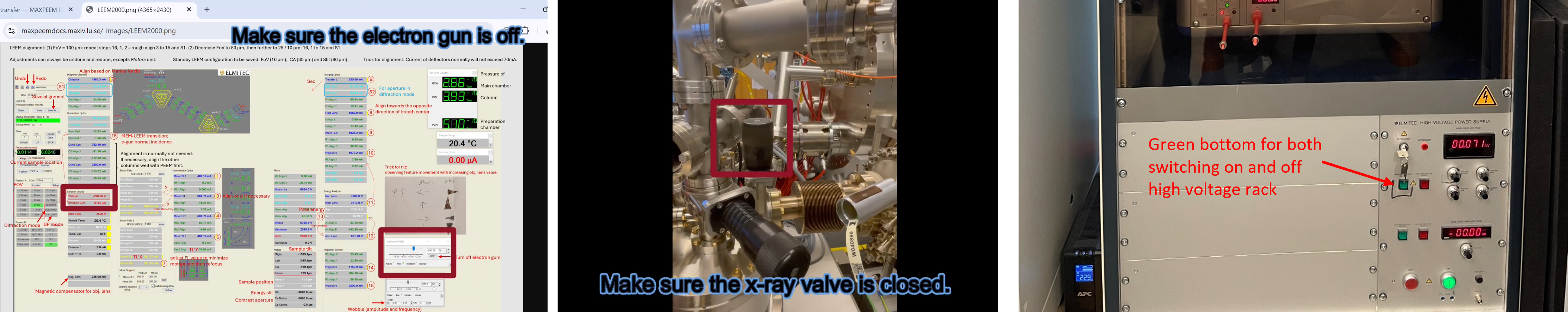
Check the pressure of chambers (Main chamber < 2x10^-9 torr), X-ray valve is closed, electron gun is off and the Start voltage is set to 0 V. Camera can be at acquisition mode. Check the sample temperature if it has been heated
Set the coarse screw to a lower value (e.g., 5) and turn on high voltage rack (HV rack). Increase slowly with eyes on pressure
UV-PEEM alignment
For rough alignment, all apertures and slit in the beam path should be removed.
Prepare the setup for UV-PEEM
Be sure the electron gun is OFF: Wehnelt potential as -360 V by default
Prepare the UV Lamp with mechanical iris being closed
Monitor the Microscope Image and Main Chamber Pressure and Slowly open the iris partially.
Caution
Be mindful of scattering and reflection of UV light.
Alignment of intermediate column
(1) Find the Optical Axis and set marker
Wobble the Mirror Transfer Lens 1 (MTL1), find breathing center and mark it.
(2) Adjust the Sample Tilt (based on marker)
Start voltage is set to 0V when start aligning tilt.
Wobble the Objective Lens and Align the breathing center to the previously set marker, minimizing image movement behind the marker.
The marker represents the optical axis. Keep in mind that image features may change while aligning the sample tilt.
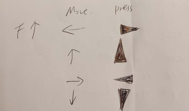
A trick to align the tilt: Observe the direction of feature movement with increasing value of objective lens and click on the corresponding bottom in the motor control panel.
If feature moving left: Click on ▷ in panel; If moving right: Click on ◁ in panel; If feature moving up: Click on ▲ in panel; If feature moving down: Click on ▼ in panel
Move a Feature to the Optical Axis (marker)
(3) Wobble Mirror Field Lens 1 (MFL1) and check
X direction: Outer sel; Y direction: MFL1 Align Y
(4) Wobble Mirror Field Lens 2 (MFL2)
(5) Wobble Mirror Transfer Lens 2 (MTL2)
Alignment of imaging column
(36) Wobble the Transfer Lens (TL)
X-axis: Mouter Se; Y-axis: Sec2 Align
(7) Wobble Minner Se and minimize the motion of reference point with FL value
(8) Wobble the Field Lens (FL) and align towards the opposite direction of breath center
(9) Wobble the Intermediate Lens (IL)
Align X if wobble in Y direction and align Y if wobble in X direction.
(10) Wobble Projective Lens 1 (P1)
Alignment in energy analyzer and projection system
(11) Wobble the Inner Lens (instead of RL)
X and Y axes: RL Align
(12) Wobble the Acceleration Lens (AL)
Center it with Sel+/-
Can try adjusting AL Align A, B but it might not help alignment
(13) Wobble Sel +/- and minimize the motion with the Acc. Lens value
This step may not help alignment. The adjustment on Acc. Lens value might decrease the image sharpness.
(14) Wobble Projective Lenses 2
(15) Wobble Projective Lenses 3
Breathing center should be centered in the image window.
Go back and check the whole column, make corrections if required.
During alignment, P3’x and y can be used for moving reference feature (optical axis) to center of view.
LEEM alignment
The setup inherited from the previous week is normally well-aligned, allowing for a simple alignment. One can start with 100 µm FoV to find the sample. Steps are marked in LEEM2000 software interface.
Prepare the setup for LEEM
Set start voltage as 0 V and Slowly decrease Wehnelt potential to observe MEM image.
Caution
Decrease the Wehnelt voltage slowly from OFF value (-360V) and observe the images.
Align Electron Gun Incidence Perpendicular to Sample
(16) Using transition from MEM to LEEM
Set start voltage to a value that provides a uniform dark spot within the bright image, and Use the ILUDX, Y deflectors to maximize and center the dark spot.
Decrease start voltage and repeat step 1 until reaches the lowest STV value (low enough value e.g., 0.5V).
Alignment of intermediate column
(1) Find the Optical Axis and set marker
Wobble the Mirror Transfer Lens 1 (MTL1), find breathing center and mark it.
(2) Adjust the Sample Tilt (based on marker)
Start voltage is set to 0V when start aligning tilt.
Wobble the Objective Lens and Align the breathing center to the previously set marker, minimizing image movement behind the marker.
The marker represents the optical axis. Keep in mind that image features may change while aligning the sample tilt.
A trick to align the tilt: Observe the direction of feature movement with increasing value of objective lens and click on the corresponding bottom in the motor control panel.
If feature moving left: Click on ▷ in panel; If moving right: Click on ◁ in panel; If feature moving up: Click on ▲ in panel; If feature moving down: Click on ▼ in panel
Move a Feature to the Optical Axis (marker)
(3) Wobble Mirror Field Lens 1 (MFL1) and check
X direction: Outer sel; Y direction: MFL1 Align Y
The incidence angle will be affected by X-direct alignment, so do previous steps to adjust back to normal incidence.
(16,1,2) Repeat the steps for perpendicular incidence (16), finding the optical axis (1), and adjusting the sample tilt (2) until no further adjustments are needed. Step 3 may need to be checked.
(16, 1→15) Check and repeat the alignment of all lens until no further adjustments are needed. Steps 4 to 15 refer to UV-PEEM alignment part or LEEM2000 software interface.
Alignment after decreasing FoV
(16, 1→15) Decrease the field of view and repeat over the checking and alignments if needed, until the desired field of view is reached.
FOV can be aligned as UVPEEM (100 µm, then 50 µm, sometimes can try 25 µm), then LEEM (50 µm, 25 µm, 10 µm). The setup inherited from previous week is normally well-aligned, and possibly standby with FOV as 10 µm. Most likely, due to the change of sample, the tilting is the most needed to be aligned.
(S1) Check the astigmatism of objective lens by adjusting Obj. stigm A, B to observe a sharper image.
One may need to adjust the objective lens to refocus. Since the Obj. stigm is to some extent coupled to illum. Defl, so check that too if using electron gun.
P3 can be used to enlarge the field of view without changing lens alignment.
Record the P3 value beforehand, so that later the value can be typed in to adjust back.
Routine alignment with LEEM
If the setup has been well aligned, but you have changed sample or you have moved a long way to a new position:
Use large field of view (75 or 100 µm) to move to the target area.
Fix the tilt using the trick marked in LEEM2000 interface: increasing the objective lens value and observe the image motion; toggle the obj lens and correct the tilt accordingly.
Insert the aperture and slit accordingly.
Slit and apertures
The apertures and slit are inserted in the sequence determined by their position along the path, e.g., CA then Slit.
(CA) Observe the PEEM/LEEM image on the screen and move the contrast aperture CA (LEEM, PEEM)
TL value and Diffraction Stigmator (S2) can be used for optimization (normally not needed).
Trick: One can remember the TL value and increase the TL value for observing image before CA insertion, e.g. 550 to 720 or even up to 800 mA. One can also remember the P3 value (e.g. 2200) and decrease it to have a larger view (e.g. 1700+).
Insert the aperture (e.g. 30 µm or larger) and center it with CA motion and CA correction in CA control panel.
One can try 100 in one direction (step=20), and change to the opposite direction if image not found. Decrease the step size and correct it until step = 2.
Toggle Interm. Lens and Acc. Lens and align them accordingly if needed.
(Slit) Insert the energy selection slit (in LEEM mode)
Can be done with UVPEEM but with LEEM is easier.
You should see a uniformly illuminated image. If not, adjust position in the slit panel, from step=20 to fine step, e.g. step=2.
(Normally not needed) If uniformly illuminated image cannot be achieved, one can try adjusting P1 value. Focus the image with FL value if needed. In DP mode, slit can be inserted for adjusting P2 and P3 to observe a sharp edge.
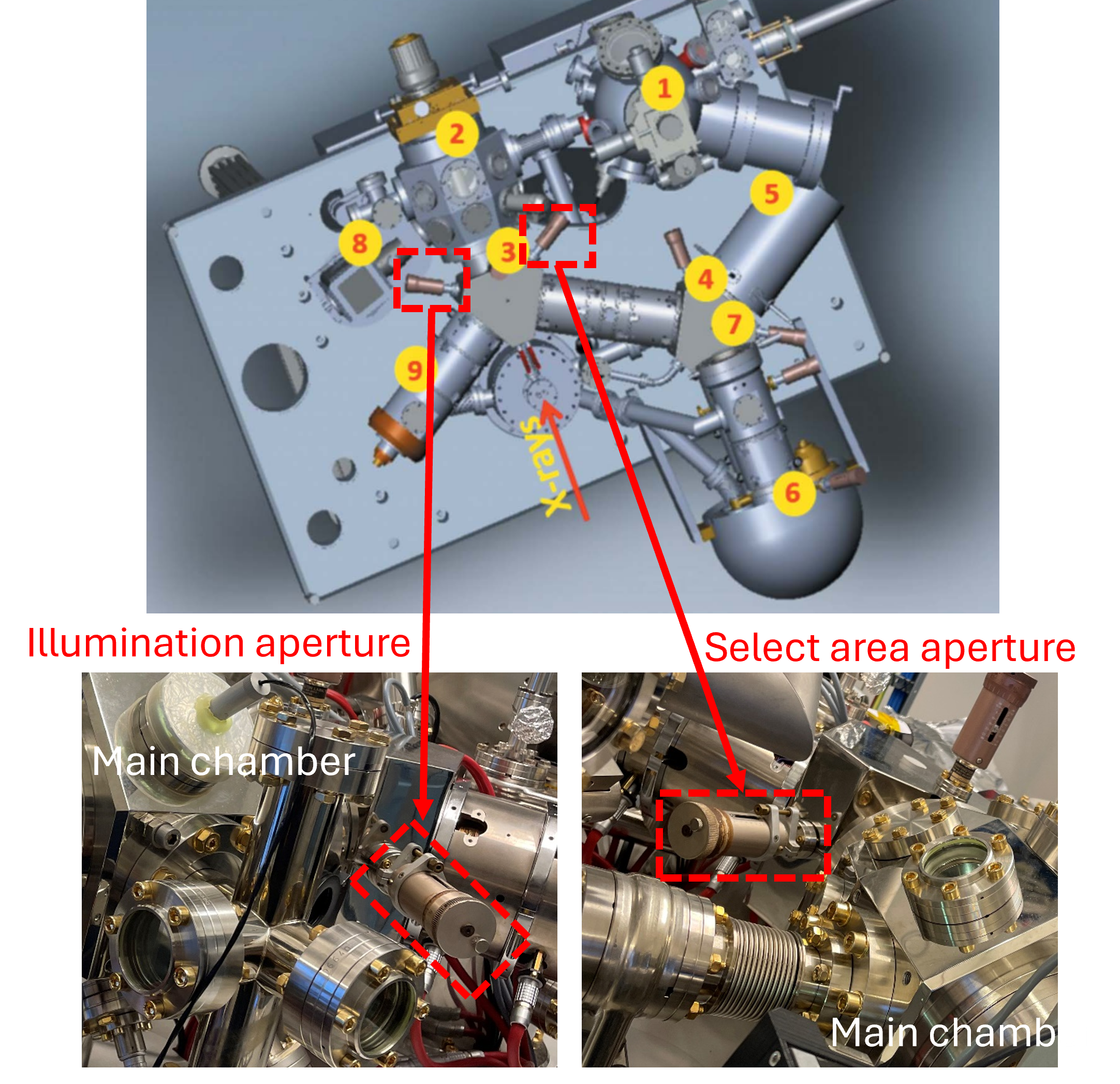
(IA) Insertion of illumination aperture (LEEM, LEED)
Location: In the first beam separator, between electron gun and sample
Observe the mirror image and move the aperture mechanism
Move the aperture and try to put it close to the center of the observed image. (Yellow) Allen key might be needed. Don’t use too much force when adjusting.
Check if the aperture is in focus otherwise correct the objective lens a little bit.
After both operations are finished check once more the image column and make corrections if required.
(SAA) Insert the select area aperture SAA
The image is enlarged 20 times, so that the real scale of observed sample image is (the size of SAA)/20.
End-of-day shutdown
Before leaving the instrument unattended, close the X-ray valve, switch off the electron gun, and power down the high-voltage rack.