Overview of beamline
Ring
The MAX IV 1.5 GeV (or R1) electron storage ring, one of the two storage rings at the Lab, is based on a compact double-bend achromat lattice and produces bright soft X-ray and ultraviolet radiation. At the center of the MAXPEEM straight section, the RMS values of the electron beam size and divergence are 184 (h) x 13 (v) um and 33 (h) x 5 (v) urad, respectively.
A schematic of the R1 ring is shown in Figure 1, relative to the LINAC and the R3 ring. The R1 ring currently hosts 5 beamlines, with room for 5 more.
Table 1. Summary of key specifications of the R1 or 1.5 GeV electron storage ring.
Parameter
Specification
Energy [GeV]
1.5
Main radio frequency [MHz]
99.931
Circulating current [mA]
500
Number of achromats
12
Circumference [m]
96
Hor. emittance (bare lattice) [pm rad]
5982
Ver. emittance [pm rad]
60
Energy spread [e-3]
0.75
Beam lifetime [hours]
10
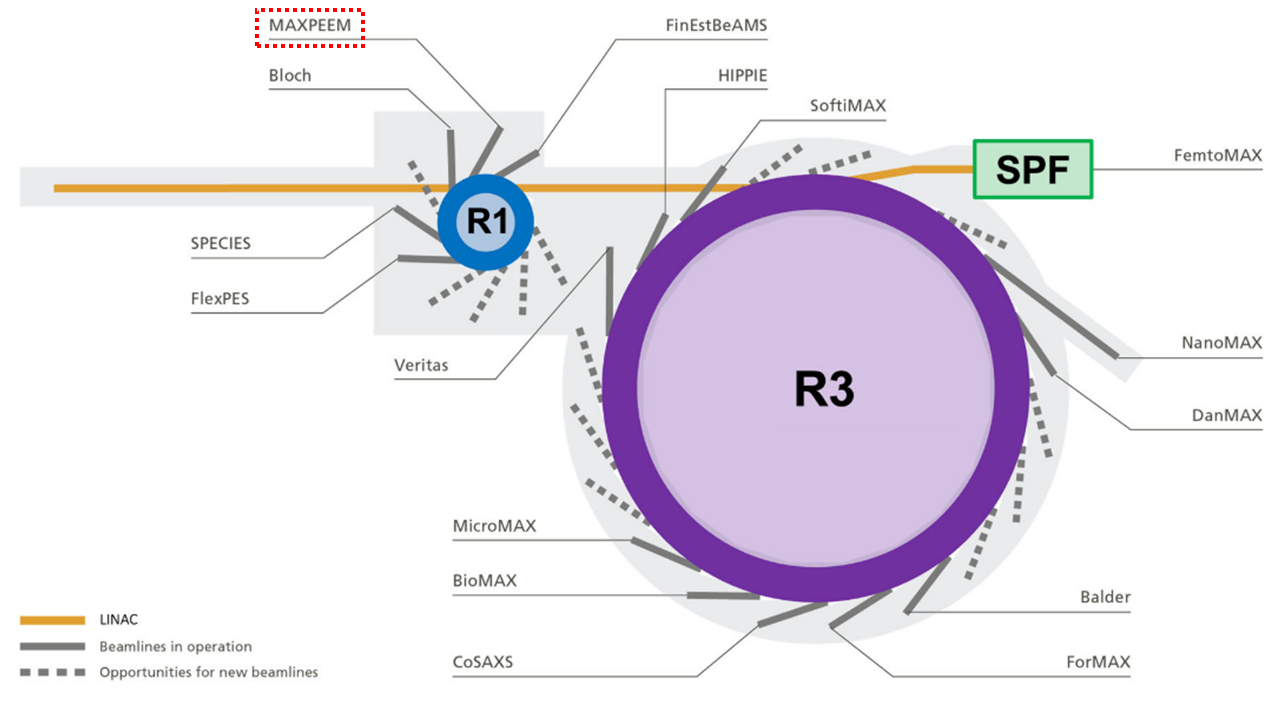
Figure 1. Schematic of MAX IV, showing the three major components: (i) linear accelerator (LINAC), (ii) 1.5 GeV electron storage ring (R1), and (iii) the 3.0 GeV electron storage ring (R3).
Beamline
A schematic of the beamline is shown in Figure 2, and the functions of the beamline elements are described in Table 2. Figure 3(a) shows the photon flux available from the beamline as a function of photon energy; the flux depends on the grating and harmonic used. The inset of Figure 3(a) shows a nitrogen K-edge absorption spectrum recorded from nitrogen gas, used to monitor the beamline resolution. Figure 2(b) shows the beam profile at the sample position, where inset (i) shows a simulation of the beam profile performed with the X-ray tracing software and inset (ii) shows the experimental beam profile in the photoelectron microscope. Figure 3(c) shows a map of the circular polarization (undulator gap versus photon energy), where the light colors indicate a higher percentage of circular polarization.
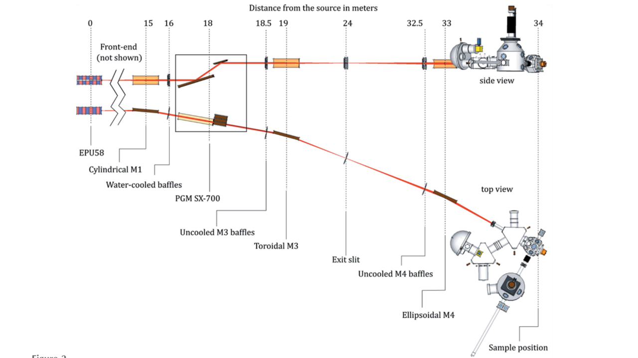
Figure 2. Schematic of the optical layout of the MAXPEEM beamline.
Table 2. Overview of key beamline elements and their functions.
Beamline element |
Description |
|---|---|
Light source |
Elliptically polarizing undulator of Apple-II type (EPU58, period length of 58 mm and 42 periods) |
Cylindrical M1 mirror |
EPU radiation deflected horizontally (by 4 deg) and collimated vertically |
Water-cooled baffles |
For reducing the horizontal and vertical acceptance of the beamline |
PGM SX-700 |
Collimated plane grating monochromator, operates with one of three plane gratings (300 l/mm, 650 l/mm, 1200 l/mm) |
Uncooled M3 baffles |
Beam-defining aperture for M3 |
Toroidal M3 mirror |
Focus the dispersed radiation both vertically and horizontally onto the exit slit |
Exit slit |
Define the beam spot size at the sample position (h x v dimensions of the beam spot on the sample is roughly 10x smaller than the h x v settings of the exit slit) |
Uncooled M4 baffles |
Beam-defining aperture for M4 |
Ellipsoidal M4 mirror |
Final refocusing onto the sample by deflecting the beam horizontally. |
Table 3. EPU58 parameters for specific modes of operation
EPU58 parameter |
Horizontal model |
Helical model |
Inclined model |
Vertical mode |
|---|---|---|---|---|
Phase [mm] |
0 |
17.38 |
16.01 |
29 |
Vert. field [T] |
0.9164 |
0.5385 |
0.3854 |
0 |
K-value |
4.964 |
2.917 |
2.088 |
3.610 |
hv [1st harmonic, eV] |
30 |
40 |
70 |
50 |
Power [kW] |
1.46 |
1.01 |
0.5 |
0.77 |
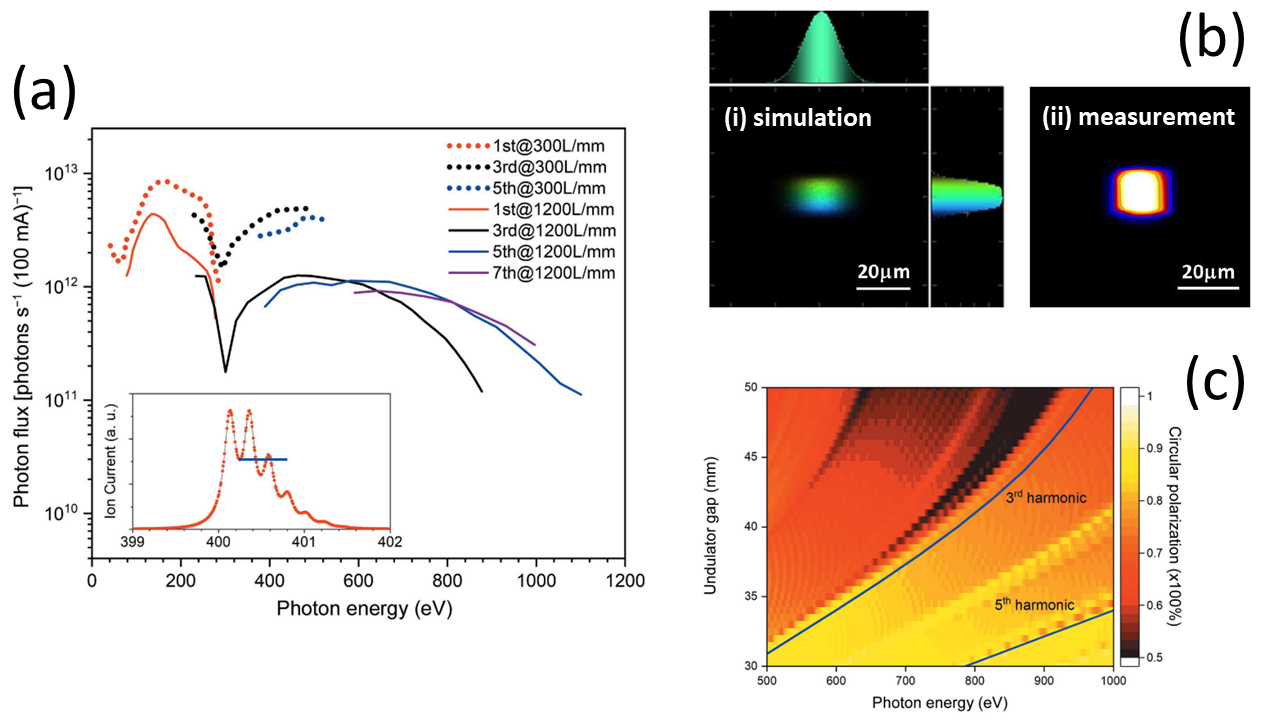
Figure 3. Several key performance parameters of the MAXPEEM beamline.
Spectro-microscopy endstation
The endstation consists of an Elmitec LEEM III direct surface imaging microscope, various upgrades to the microscope (e.g. aberration corrector, larger energy analyzer for improved energy resolution (R200 versus R100), higher pixel count CMOS camera detector, motorized manipulator, etc.), and vacuum chambers added in-house (e.g. preparation and storage chambers). A top view schematic of the endstation is shown in Figure 4.
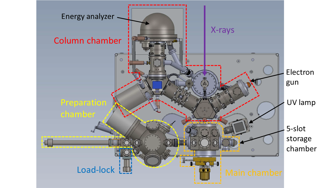
Figure 4. Top view schematic of the MAXPEEM spectro-microscopy endstation, showing key vacuum chambers and the three (photo-)excitation sources: (i) beamline, (ii) UV lamp and (iii) electron gun.
The following actions can be performed in the prep chamber:
material deposition,
LEED measurements,
gas dosing, and
sputtering and annealing up to 2000 K.
The microscope can perform live imaging:
while the sample temperature is varied (89 K to 1600 K),
under operando conditions (varying magnetic field, applied electric potential, etc.), and/or
while metals/molecules/etc. are deposited.
The most important imaging modes of the microscope are summarized in Table 4. One of the most powerful aspects of this instrument is that it can image a given sample with structural, chemical, electronic and magnetic contrast.
Table 4. Summary of the key imaging modes of the microscope.
Operation mode |
Information yielded |
|---|---|
X-ray Photoemission Electron Microscopy (XPEEM) |
Energy filtered imaging. The technique can be used for slow secondary electrons (utilizing a work function contrast) as well as for core-level electrons characteristic of the studied material. This allows for performing elemental/chemical mapping. |
X-ray Magnetic Circular/Linear Dichroism (XMCD/XMLD) |
Utilizing the circular polarization of the photon beam to exploit the magnetic circular dichroism effect (MCD), the imaging of magnetic domains in ferromagnets is possible on the nanometer scale (XMCD-PEEM). Using the linear polarization of the photon beam to exploit the magnetic linear dichroism (MLD) effect, magnetic domains in antiferromagnets can also be imaged on the same scale. |
Micro X-ray Photoemission Spectroscopy (micro-XPS) |
Valence band and/or core level photoemission spectroscopy from extremely small areas down to a fraction of a micron. High flux on the samples yields both high spatial and high energy resolution. |
Micro X-ray Absorption Spectroscopy (micro-XAS) |
The microscope images the secondary electron emission at fixed kinetic energy as a function of the photon energy, enabling spatially-resolved X-ray absorption spectroscopy (XAS or NEXAFS). |
PhotoElectron Diffraction (PED) |
The intensity of a core level line as a function of energy and emission angle is measured. The technique can provide spatially resolved information on the surface crystallographic structure and is therefore complementary to LEED and STM. |
Micro Angle Resolved Photoemission Spectroscopy (micro-ARPES) |
If the valence band electrons form a diffraction pattern, the band- and Fermi surface mapping in the full cone become possible. |
Low Energy Electron Microscopy (LEEM) |
This is one of the most powerful techniques for imaging the morphology of crystalline surfaces. Several contrast mechanisms (including Dark Field Imaging) allow the determination of the lateral dimensions of regions with a given crystal structure, the thickness distribution of thin overlayers with monolayer resolution, the imaging of monoatomic surface steps and other morphological features. |
Micro Low Electron Energy Diffraction (micro-LEED) |
By simply switching one lens and removing the contrast aperture the LEED pattern of the imaged area can be obtained. The imaged area can be as small as 100 nm, so the diffraction pattern from such a small area can be obtained. |
Further reading
Leemann, S. C. Recent Progress on the MAX IV 1.5 GeV Storage Ring Lattice and Optics. IPAC 2012 - Int. Part. Accel. Conf. 2012, 1662–1664.
Zakharov, A.; Preobrajenski, A.; Sankari, R. MaxPEEM Beamline (1.5 GeV Ring at MAX IV) Detailed Design Report; 2014.
Robert, A.; Cerenius, Y.; Tavares, P. F.; Hultin Stigenberg, A.; Karis, O.; Lloyd Whelan, A.-C.; Runéus, C.; Thunnissen, M. MAX IV Laboratory. Eur. Phys. J. Plus 2023, 138 (6), 495. https://doi.org/10.1140/epjp/s13360-023-04018-w
Niu, Y.; Vinogradov, N.; Preobrajenski, A.; Struzzi, C.; Sarpi, B.; Zhu, L.; Golias, E.; Zakharov, A. MAXPEEM: A Spectromicroscopy Beamline at MAX IV Laboratory. J. Synchrotron Radiat. 2023, 30 (2), 1–11. https://doi.org/10.1107/S160057752300019X
Niu, Y.; Golias, E.; Man, G.; Zakharov, A. MAX IV Beamline Review Report: MAXPEEM; Lund, Sweden, 2023. https://www.maxiv.lu.se/wp-content/plugins/sharepoint-plugin/ajax/downloadFile.php?site_id=MAXIV&version_series_id=16&repository_id=0df38c7e-6f77-43c7-8ab8-bd7153273666
Nyholm, R.; Andersen, J. N.; Johansson, U.; Jensen, B. N.; Lindau, I. Beamline I311 at MAX-LAB: A VUV/Soft X-Ray Undulator Beamline for High Resolution Electron Spectroscopy. Nucl. Instruments Methods Phys. Res. Sect. A Accel. Spectrometers, Detect. Assoc. Equip. 2001, 467–468, 520–524. https://doi.org/10.1016/S0168-9002(01)00399-0.
Bauer, E. Surface Microscopy with Low Energy Electrons; Springer New York: New York, NY, 2014; Vol. 9781493909. https://doi.org/10.1007/978-1-4939-0935-3.